
Smart Home Security System using Arduino and SIM800 GSM/GPRS Module is all about monitoring home from remote place by making call and SMS. I’ll explain how it works and how to interface GSM module,PIR motion sensor,MQ2 sensor,rain-drop sensor with Arduino and circuit diagram. start with block diagram.

Block Diagram :

Material Used In This Project:
(1) Arduino uno-Board.
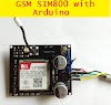
(2) SIM800 GSM Module.
(3) PIR (HC-SR501 Motion Sensor) x 2.
(4) MQ-2 gas Sensor.
(5) Rain Sensor.
(6) Jumper cable.
Basic Diagram:
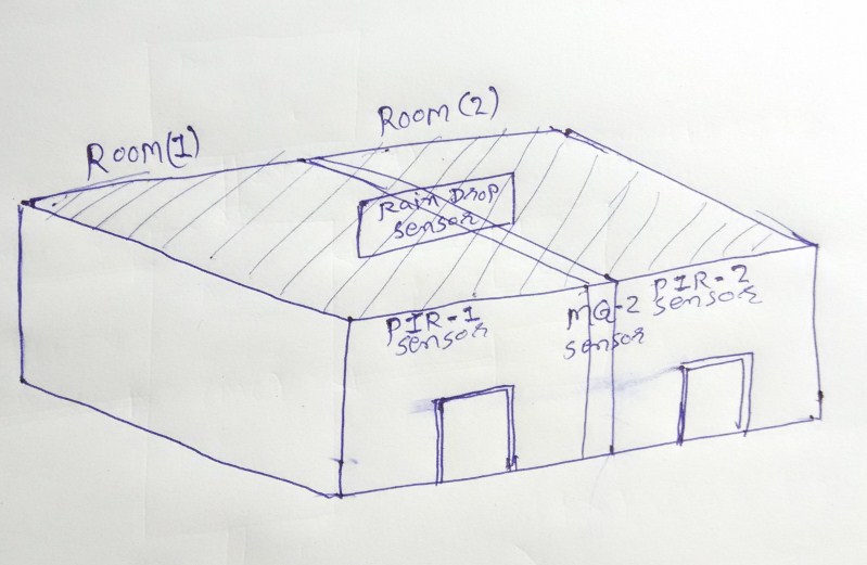
In Smart Home Security System project Arduino continues scan the both PIR-Motion Sensor ,Raindrop sensor and MQ-2 sensor .The PIR Sensor is a pyroelectric device that detects motion ,if motion is present in any room then appropriate PIR sensor gives the output, according to a motion detected GSM module send The SMS to a particular number and after make call to this number.
The rain sensor module is used to rain detection. When rain falling in the sensor plate it’s gives the output. According to this controller send the alert message to particular number.
The MQ-2 gas sensor is sensitive to LPG, i-butane, propane, methane, alcohol, Hydrogen and smoke. When any one of this Gas is present in the room sensor gives the output. According to this Controller send the alert SMS to particular number.
GSM/GPRS Module:
SIM800 is a complete Quad-band GSM/GPRS solution in a SMT type which can be embedded in the customer applications. SIM800 support Quad-band 850/900/1800/1900MHz, it can transmit Voice, SMS and data information with low power consumption. With tiny size of 24*24*3 mm, it can fit into slim and compact demands of customer design. Featuring Embedded AT, it allows total cost savings and fast time-to-market for customer applications.


PIR Sensor:
PIR sensors allow you to sense motion, almost always used to detect whether a human has moved in or out of the sensors range. They are small, inexpensive, low-power, easy to use and don't wear out. For that reason they are commonly found in appliances and gadgets used in homes or businesses. They are often referred to as PIR, "Passive Infrared", "Pyroelectric", or "IR motion" sensors.
PIRs are basically made of a pyroelectric sensor (which you can see below as the round metal can with a rectangular crystal in the centre), which can detect levels of infrared radiation. Everything emits some low level radiation, and the hotter something is, the more radiation is emitted. The sensor in a motion detector is actually split in two halves. The reason for that is that we are looking to detect motion (change) not average IR levels. The two halves are wired up so that they cancel each other out. If one half sees more or less IR radiation than the other, the output will swing high or low.


MQ-2 Sensor :
The MQ-2 Gas sensor can detect or measure gasses like LPG, Alcohol, Propane, Hydrogen, CO and even methane. The module version of this sensor comes with a Digital Pin which makes this sensor to operate even without a microcontroller and that comes in handy when you are only trying to detect one particular gas. When it comes to measuring the gas in ppm the analog pin has to be used, the analog pin also TTL driven and works on 5V and hence can be used with most common micro-controllers.


Rain Sensor:
The rain sensor module is an easy tool for rain detection. It can be used as a switch when raindrop falls through the raining board and also for measuring rainfall intensity. The raindrop sensor module is used for rain detection. It is also for measuring rainfall intensity. The module includes a rain board and a control board that are separate for more convenience. It has a power indicator LED and an adjustable sensitivity though a potentiometer. The module is based on the LM393 op amp. It includes a printed circuit board(control board) that “collects” the rain drops. As rain drops are collected on the circuit board, they create paths of parallel resistance that are measured via the op amp. The lower the resistance (or the more water), the lower the voltage output.Conversely, the less water, the greater the output voltage on the analog pin. A completely dry board for example will cause the module to output five volts.


Wire Diagram:


Connection with Arduino Uno:
Connect Vcc pin of all sensor and GSM/ GPRS module to the 5V, DC (1-2 A) Power supply. And GND to the Ground of the Power supply.
Connect “D0” pin of PIR-1 sensor to the digital pin-D3 of arduino UNO.
Connect “D0” pin of PIR-2 sensor to the digital pin-D2 of arduino UNO.
Connect “AO” pin of MQ-2 sensor to the analog pin-A0 of arduino UNO.
Connect “AO” pin of Rain sensor to the analog pin-A1 of arduino UNO.
GSM/GPRS Module
Connect “RX” pin of GSM module to the digital pin-10 of arduino UNO.
Connect “TX” pin of GSM module to the digital pin-9 of arduino UNO.
Note: hear we used the software serial. So we used the digital pin-9 as a serial Receive and pin-10 as a Serial Transmit.
This all connection is also given in wire diagram.
When connection is completed, turn ON the power supply and wait for few second to initialise the GSM/GPRS module. When blinking of network LED is slow and blink time is very short.That means the Module is connected to the network and it’s ready to use.
Arduino Code:
------------------------------------------------------------------------------
#include <SoftwareSerial.h>
#define PIR_1 3
#define PIR_2 2
#define RAIN_DROP A1
#define MQ_2 A0
#define RAIN_LIMT 800 // value at witch rain alarm fire.
#define MQ_2_LIMIT 150 // value at witch smoke alarm fire.
SoftwareSerial mySerial(9, 10); //(RX,TX)
volatile unsigned int SMOK_VALUE = 0,RAIN_VALUE = 0;
double previous_time = 0,time = 0;
void setup()
{
mySerial.begin(9600); // Setting the baud rate of GSM Module
Serial.begin(9600); // Setting the baud rate of Serial Monitor (Arduino)
pinMode(PIR_1,INPUT);
pinMode(PIR_2,INPUT);
Serial.println("Hello Friend...!!");
delay(8000);
mySerial.println("AT+CMGF=1\r\n");// set to Text mode.
delay(500);
mySerial.println("AT+CSCS=\"GSM\"\r\n"); // set TE character set
delay(200);
previous_time = -30000;
}
void loop()
{
if(digitalRead(PIR_1) == 1)// scan Pir-1 sensor.
{
delay(100);
if(digitalRead(PIR_1) == 1)
{
time = millis();
if(time - previous_time > 30000)// wit for the 30 second.
{
Serial.println("PIR 1 on!!");
SendMessage1();
previous_time = millis();
}
}
}
else if(digitalRead(PIR_2) == 1)// scan Pir-2 sensor.
{
delay(100);
if(digitalRead(PIR_2) == 1)
{
time = millis();
if(time - previous_time > 30000)
{
Serial.println("PIR 2 on!!");
SendMessage2();
previous_time = millis();
}
}
}
else if(analogRead(RAIN_DROP) <= RAIN_LIMT)// scan rain sensor.
{
delay(10);
if(analogRead(RAIN_DROP) <= RAIN_LIMT)
{
time = millis();
if(time - previous_time > 30000)
{
RAIN_VALUE = analogRead(RAIN_DROP);
Serial.print("Rain coming value is : ");
Serial.println((int)RAIN_VALUE);
SendMessage_RAIN();
RAIN_VALUE = 0;
previous_time = millis();
}
}
}
else if(analogRead(MQ_2) >= MQ_2_LIMIT)// scan MQ-2 sensor.
{
delay(10);
if(analogRead(MQ_2) >= MQ_2_LIMIT)
{
time = millis();
if(time - previous_time > 30000)
{
SMOK_VALUE = analogRead(MQ_2);
Serial.print("Do not smoke Value is : ");
Serial.println((int)SMOK_VALUE);
SendMessage_SMOKE();
SMOK_VALUE = 0;
previous_time = millis();
}
}
}
if (mySerial.available()>0)//receive software serial data.
Serial.write(mySerial.read());//print software serial data.
}
void SendMessage1()
{
mySerial.print("AT+CMGS=\"+91xxxxxxxxxx\"\r"); // Replace xxxx with your mobile number//
delay(500);
mySerial.print("hi be alert. some stranger entering in your room-1.\r\n");// The SMS text you want to send
delay(500);
mySerial.print((char)26);//((char)26);// ASCII code of CTRL+Z
delay(8000);
mySerial.print("ATDxxxxxxxxxx;\r\n");// AT command for call // Replace xxxx with your mobile number
delay(200);
// mySerial.print("ATH\r\n");
}
void SendMessage2()
{
mySerial.print("AT+CMGS=\"+91xxx\"\r"); // Replace xxx with mobile number
delay(500);
mySerial.print("hi be alert. some stranger entering in your bed room.\r\n");// The SMS text you want to send
delay(500);
mySerial.print((char)26);//((char)26);// ASCII code of CTRL+Z
delay(8000);
mySerial.print("ATDxxxxxxxxxx;\r\n");// AT command for call // Replace xxxx with your mobile number
delay(500);
// mySerial.print("ATH\r\n"); // At command for cut the call.
// delay(200);
}
void SendMessage_RAIN()
{
mySerial.print("AT+CMGS=\"+91xxxxxxxxxx\"\r"); // Replace x with mobile number//
delay(500);
mySerial.print("It's raining on you house.\n value is : \r");// The SMS text you want to send
mySerial.println((int)RAIN_VALUE);//print the sensor value.
delay(500);
mySerial.print((char)26);//((char)26);// ASCII code of CTRL+Z
delay(500);
}
void SendMessage_SMOKE()
{
mySerial.print("AT+CMGS=\"+91xxxxxxxxxx\"\r"); // Replace x with mobile number//
delay(500);
mySerial.print("Check your gas stove it's not closed or your House is in fire check quickly before serious.Value is : \r");// The SMS text you want to send
mySerial.println((int)SMOK_VALUE);//print the sensor value.
delay(500);
mySerial.print((char)26);//((char)26);// ASCII code of CTRL+Z
delay(500);
}
------------------------------------------------------------------------------
Put this code in Arduino IDE, save and compile this sketch. After success full compilation upload the sketch on Arduino UNO board. Wait some second and check it.


1 Comments
OTIMO PROJETO , TEM COMO ACIONAR UMA SIRENE E DESLIGAR E LIGAR UM RELE VIA SMS, OBRIGADO
ReplyDelete